Control high voltage device with arduino and IR remote control
There are lots of sensors that we can play around with Arduino but usually, they operate on 3.3v or 5v but what if you want to control high voltage circuits that don’t operate on such low voltage. Well for these types of devices we use relay circuits. There are different types of Relay circuits with based on parameters like how much current/voltage it can handle, what is the voltage required for controlling their relay etc. The relay circuit we are going to use for this post is operating on 5V and can handle device having a voltage rating of 10A-125V to 10A-230V AC and 10A-28V to 10A-30V DC.
#Motivation
Long time ago when I was first introducted to mini development boads I was reading about raspberry pi DIY projects, and I came across home automation project which to me was very fascinating, reading further on the topic I realised there are zigbee and z-wave products for commuincation and controlling home appliances which made the whole project costly some of the products were even costly then raspberry pi itself. Later I can across arduino and relay circuits which made my hopes of affordable home automation come alive. Most of home appliance work within 230V in India which can be controlled by Arduino which help of relay circuits.
#Project Ideas
In this post, we will control relay circuit with Arduino. We will use 4 channel relay circuit which will allow us to control up to 4 devices operating within the relay rating. We need to feed some input to Arduino to indicate which relay channel to turn on/off for that we will use IR remote control and attach an IR receiver LED to Arduino to receive the infrared signal from the remote. We will bind 4 keys of IR remote control to 4 channels of the relay by programming Arduino.
#Components required
- Arduino Uno
- Relay circuit (of rating 125v to 230v AC and 28V to 30V DC)
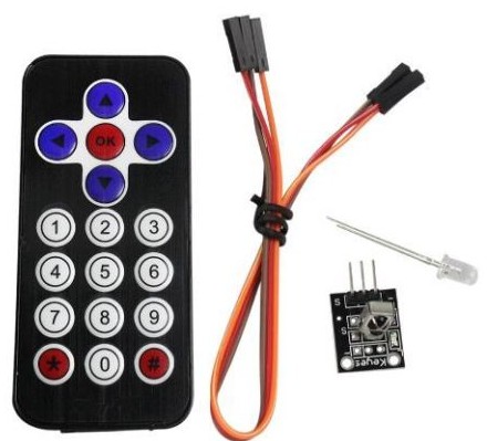
- IR remote control
- IR receiver module
- breadboard
- jumper wires
#Accepting commands from IR remote control

First, we need to identify codes of at least four buttons on IR remote control. For that, we will read data from the signal pin of IR receiver module connected to Arduino on pin 11 when a particular button is pressed. The code for this is as below :
Download IR receiver LED library from this link. Import the library in your Arduino IDE (Sketch -> Import Library -> IR).
1 |
|
Above code will print IR remote button code in hexadecimal on the serial monitor. Take note of codes any four buttons which you want to use. This setup can also read button codes of other IR remote control in your house like Air Condition or Television remote. So you can even use your TV remote to control our relay circuit.
The button codes which we read through this code may or may differ for different remote control, so it’s necessary to the above exercise to get codes of the buttons.
#Using Relay circuit to control HIGH voltage device
For an electrical device to run it has to form a close path for current to flow if we break the circuit(open path) current stops electrical device turned off this working this how switches work. When you turn on the switch it forms a close path and the device turned on and vice versa. With relay circuits, we can do this thing programmatically.
If you look closely in the image above, it has two terminal operating at different voltages, a HIGH voltage terminal where the device will be connected(upper side) and LOW voltage terminal which will be connected to Arduino (bottom right). In our case we are using 4 channel relay circuit, each channel has three HIGH voltage terminals (NC, NO, and C). To control the device we break the circuit and connect one end of the wire to C (common connection) terminal on one channel of the relay circuit. Relay offers two close paths, we connect our other end of device wire to one of the terminals NC (normally closed) or NO (normally open). NC forms close configuration when Arduino sends the HIGH signal to relay’s corresponding signal pin and NO forms close configuration when Arduino sends LOW or signal. Each relay can form close configuration with either NC or NO at any instance of time not with both at the same time. So if you want to turn on the device when Arduino sends a LOW signal then connect the other end of the device with NC pin.
Now that we know the purpose of HIGH voltage pins. Let see how low voltage terminal influences the electrical path of HIGH voltage terminals. Low voltage path is controlled by Arduino digital pin. If Arduino send’s a HIGH signal to the signal pin on the relay circuit the electromagnet becomes charged and moves the switch, which in turn form a close configuration with NO pin, putting relay circuit in activated state which starts the flow of current in the device. Relay circuit in activated state forms close configuration with NO pin and in deactivated state close configuration with NC pin. In a similar manner, each relay circuit has a corresponding signal pin which is connected to the digital pin of Arduino board. Below is the working diagram of the relay circuit.

#Relay circuit Schematic diagram
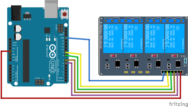
Below is the schematic diagram of relay circuit interfaced with Arduino

The code below will turn on each relay circuit at a 3-second interval. Here we are just simply turning on the circuit without any external input. We can also turn on/off the relay circuit when certain conditions are met like if the temperature sensor is reading of 23 deg and above we could turn on the fan or if a PIR sensor detects a person has entered the room so turn on the light, etc. In our case, we will turn on/off the relay circuit based on the button pressed on IR remote control.
1 | int CHANNEL_1 = 6; |
#Putting it all together
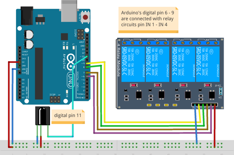
Finally we are in position of make IR remote control and relay circuit to work together. Below is the schematic diagram the circuit.

You can change button code below with the button code you have discovered for your remote control other pin configurations are in the variables. You can directly copy paste and the below sketch in your Arduino IDE and upload the code.
1 |
|
#Conclusion
We saw how we can control high voltage devices with Arduino IR remote control. You can even extend this project to control the relay circuit with your mobile device, wireless communication between mobile and Arduino can be taken care by using ESP8266 module here is the link to post. Electrical circuits used in this post are available for a couple of bucks so making a home automation project is really not that costly.