Connecting ESP8266-01 with Arduino UNO via Software serial
If you ever heard of internet of a thing and have been fascinated by its possibilities and its promises then I am sure you must have heard of Arduino development boards. Arduino is a great piece of hardware to do some quick hardware prototyping and when you are confident with the prototype you go a step further and build more of these devices and make them work for you to do some sort of automation. Adding Wireless capability to Arduino projects will even make it more easy to install/use. In this post, I will connect the ESP8266 chip to Arduino Uno. We will see how we can create Access Point and connect to wireless networks. ESP8266 is a low-cost alternative to Arduino WiFi shield.
#Components required :
- Arduino Uno
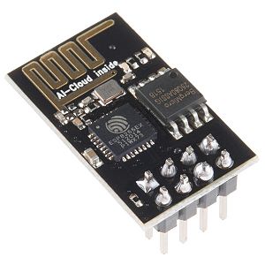
- ESP8266-01
- Bread board
- Couple of jumper wires
#Little introduction to ESP8266-01:
ESP8266 is a low-cost WiFi chip with full TCP/IP stack and micro-controller unit capability. That means this chip can connect to a Wireless network or could act as an Access point, going a step further it could be a web server displaying sensor data of the sensor attached to it. All these features can be used just using this standalone chip just adding 3.3v power to it.

#The feature list includes:
- 802.11 b/g/n protocol
- Wi-Fi Direct (P2P), soft-Access Point
- Integrated TCP/IP protocol stack
#Going into technical specs:
- CPU - 80 MHz(default) or 160Mhz
- Memory - 64 KiB instruction, 96 KiB data
- Input - 16 GPIO pins
- Power - 3.3 Voltage and 200mA current
We can reprogram this chip with different SDK’s. There are lots of different SDK’s out there like:
- NodeMCU - A Lua based firmware
- Arduino - A C++ based firmware if you like Arduino style programming
- MicroPython - for the love of Python it’s a port of Python for embedded devices which is also ported to ESP8266
there are many more. One limitation of this chip is that in this version only 2 GPIO pins are exposed although there are 16 GPIO pins which could be used.
#Connecting Arduino to ESP8266-01:
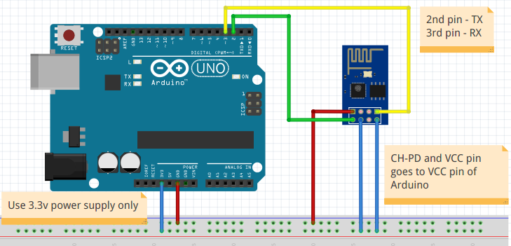
We will connect Arduino to esp8266 via a software serial and try different AT commands. With AT commands we can connect to wireless network and create Access points, etc. But first follow the pin diagram below and make connections and be careful about the VCC connection don’t connect it to 5V or you are going to fry the ESP8266 chip (chips are already fried;).

Upload the following sketch to your Arduino
1 |
|
Once you have made the connections open up the serial console and power up your Arduino you should be able to see a red light on the ESP8266 indicating it is powered and should display random character printing on the serial console this means congratulations connection is made successfully. Now let’s try out different AT commands.
Open Tools > Serial Monitor in your Arduino IDE and set Both NL & CR and Baud to 115200 or whatever baud rate you have set in the code or else you won’t see any output.
I am using latest firmware v1.154 version which has an additional feature which is highlighted in the AT-commands sections below. Default baud rate for this firmware is 115200.
#AT-commands Primer :
#Basic commands (Hello 123 mike testing!) :
- Test for startup type
ATresponse will returnOK. AT-RSTwill reset the module return will be a whole lot of information about the module.AT-GMRcheck firmware version
response :
1 | <AT version info> |
AT-GSLP=<time>enter deep sleep mode (why not save some power): esp8266 will wake after deep sleep for as many milliseconds(ms) in time indicates response will be<time> OK
#Wi-Fi AT Commands :
With new SDK certain old commands are deprecated and new commands are available usually prepended by _CUR if the configuration not to be saved on flash memory and _DEF if the configuration has to be saved on flash memory.
-
Set the Wi-Fi Mode (Station/AccessPoint/Station+AccessPoint):
command :
AT+CWMODE[_CUR/_DEF]=<mode>:CODE MODE 1 Station mode 2 AccessPoint mode 3 AccessPoint+Station mode response
OKexample -
AT+CWMODE_DEF=3will make the chip act as both station and Access point this setting will be saved on flash memory as the chip will start in this mode even after the restart. -
Connecting to as Access Point :
command :
AT+CWJAP[_CUR/_DEF]=<ssid>,<pwd>[,<bssid>]
Parameters:- `
': the SSID of the target AP. - `
': password, MAX: 64-byte ASCII. - `
': the target AP’s MAC address, used when multiple APs have the same SSID. <error code>: (for reference only)- connection timeout.
- wrong password.
- cannot find the target AP.
- connection failed.
response -
OKexample -
AT+CWJAP_CUR="abc","0123456789","ca:d7:19:d8:a6:44"will connect to access point with ssid abc and password 0123456789 and bssid ca:d7:19:d8:a6:44 and configuration will not be saved on the flash. - `
-
Lists Available Access Points :
command :
AT+CWLAP=<ssid>[,<mac>,<ch>],<ecn>,<ssid>,<rssi>,<mac>,<ch>,<freq offset>,<freq calibration>- it also provide ability to query the access points with specific SSID and MAC on specific channelParameters:
-
<ecn>: encryption method :CODE METHOD 0 OPEN 1 WEP 2 WPA_PSK 3 WPA2_PSK 4 WPA_WPA2_PSK 5 WPA2_Enterprise (AT can NOT connect to WPA2_Enterprise AP for now.) -
<ssid>: string parameter, SSID of the AP. -
<rssi>: signal strength. -
<mac>: string parameter, MAC address of the AP. -
<freq offset>: frequency offset of AP; unit: KHz. The value of ppm/2.4. -
<freq calibration>: calibration for the frequency offset.
response -
OKexample -
AT+CWLAP="Wi-Fi"search for APs with a designated SSID. -
-
Lists Available Access Points :
AT+CWLAP -
Disconnects from the AP command
AT+CWQAP -
Configures the ESP8266 Access Point:
command :
AT+CWSAP[_CUR/_DEF]=<ssid>,<pwd>,<chl>,<ecn>,<max conn>,<ssid hidden>Parameters:
-
<ssid>: string parameter, SSID of AP. -
<pwd>: string parameter, length of password: 8 ~ 64 bytes ASCII. -
<chl>: channel ID. -
<ecn>: encryption method: WEP is not supported.CODE ENC TYPE 0 OPEN 2 WPA_PSK 3 WPA2_PSK 4 WPA_WPA2_PSK -
[<max conn>](optional): maximum number of Stations to which ESP8266 SoftAP can be connected; within the range of [1, 4]. -
[<ssid hidden>](optional):CODE DESC 0 SSID is broadcasted. (the default setting) 1 SSID is not broadcasted
response -
OKexample :
AT+CWSAP_DEF="ESP8266","1234567890",5,3creates access point with designated name and password on channel 5 with WPA2_PSK encryption. -
#TCP/IP-Related AT Commands :
To try this commands first connect to a Wireless network using the command shown in the above section
-
Enable multiple connections :
AT+CIPMUX=1 -
Find out the IP address of the module :
AT+CIFSR -
Establishes TCP Connection, UDP Transmission or SSL Connection :
command :
AT+CIPSTART=<type>,<remote IP>,<remote port>[,<TCP keep alive>]Parameters :
<type>: string parameter indicating the connection type: “TCP”, “UDP” or “SSL”.<remote IP>: string parameter indicating the remote IP address. Parameters.<remote port>: the remote port number.[<TCP keep alive>]: detection time interval when TCP is kept alive; this function is disabled by default. 0 to disable TCP keep-alive. 1 ~ 7200 - detection time interval; unit: second (s).
-
Listen for a connection on a specific port: command
AT+CIPSERVER=<mode>,<port>mode 1 is to create server and 0 is to delete the server. -
Send data on TCP connection:
AT+CIPSEND- Sends Data on the TCP connection on which you were Listening on (read manual in the link for more details).
#Conclusion:
We saw how we could add wireless capability to Arduino project and using the above command we can create network connections read and write data(sensor data/commands) to and from a server, which gives us full TCP/UDP networking capability. I would highly recommend you to read the manual to explore various other commands and have fun with it. In the next post I will show how we can read sensor data and send it to the central server and display its data on a mobile application.