Sensing current using Hall Effect Current sensor ACS712 and Arduino
Browsing through Arduino projects on the internet recently I came across ACS712 current Hall sensor which can be used to measure current, it can measure both AC and DC current.I found it pretty cool so I ordered one, this post is about how we can measure AC/DC current consumed by the load connected to the power supply. So of the other applications of the sensor that comes to my mind are sensing if a device is on/off, measure instability in power supply, motor control, over current fault protection, etc.
#Features list includes
- Low-noise analog signal path
- Device bandwidth is set via the new FILTER pin
- 5 µs output rise time in response to step input current
- 80 kHz bandwidth
- Total output error 1.5% at TA = 25°C
- Small footprint, low-profile SOIC8 package
- 1.2 mΩ internal conductor resistance
- 2.1 kVRMS minimum isolation voltage from pins 1-4 to pins 5-8
- 5.0 V, single supply operation
- 66 to 185 mV/A output sensitivity
- Output voltage proportional to AC or DC currents
- Factory-trimmed for accuracy
- Extremely stable output offset voltage
- Nearly zero magnetic hysteresis
- Ratiometric output from supply voltage
#Required Components:
- Arduino Uno
- Current Hall Sensor ACS712
- Breadboard
- Jumper wires
#About Hall Effect Current sensor ACS712
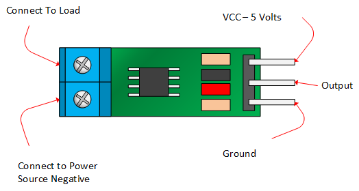
The picture below identifies the pin outs for the ACS172 modules.

The sensor consists of a linear Hall circuit with a copper conduction path located near the surface of the chip. When the device is turned on the applied current flowing through the copper conduction path which generates a magnetic field which the sensor converts into a linearly proportional voltage. This voltage is read through the Arduino analog pin which outputs 10-bit number (0-1023), from which the DC or AC current can be calculated.
Table below give specification on the different version of the chip
| 5A Module | 20A Module | 30A Module | |
|---|---|---|---|
| Supply Voltage (VCC) | 5Vdc Nominal | 5Vdc Nominal | 5Vdc Nominal |
| Measurement Range | -5 to +5 Amps | -20 to +20 Amps | -30 to +30 Amps |
| Voltage at 0A | VCC/2 (nominally 2.5Vdc) | VCC/2 (nominally 2.5Vdc) | VCC/2 (nominally 2.5VDC) |
| Scale Factor | 185 mV per Amp | 100 mV per Amp | 66 mV per Amp |
| Chip | ACS712ELC-05A | ACS712ELC-10A | ACS712ELC-30A |

Sensor IC is electrically isolated from the terminals conducting path. This feature allows, applications requiring electrical isolation without the use of opto-isolators or other costly isolation techniques.
The voltage reading on the Arduino analog pin by the sensor depends on the sensor’s rating. The ±5A sensor will output 185mV for each amp (mV/A), the ±20A 100mV/A and the ±30A 66mV/A. Accurately knowing the voltage is therefore pretty important. I bought 30A version so output will be 66mV/A.
#Schematics
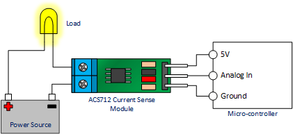
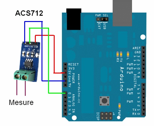
The connection of ACS712 with Arduino and load is shown below.

#Sensing DC Current
Sensing DC current is simple as there is no change in direction of current with it is as simple as reading the value from the Arduino’s analog pin to which sensor is connected. The code for the Arduino is below
1 | const int analog_IN = A0; |
If your load used the DC power supply then you should use the code above to measure the current.
#Sensing AC Current
Sensing AC current is a bit complex as the direction is constantly reversing in each sinusoidal cycle so we will get different current value each time we read the value. Instead, we are interested in Root mean square Voltage (Vrms).
With Arduino, we can continuously fetch readings from the analog pin for 1 second and get the highest reading in that interval. As the sin wave has a known frequency of 50/60 Hz sampling two waves will be good enough. This will give us peak voltage (Vp) in both(negative and positive) direction. RMS voltage can be calculated using peak voltage Vrms = Vp / √2. The code below reads samples for both minimum and maximum voltage for better accuracy, peak voltage Vp is the average of the absolute value of two voltages :
1 |
|
#Conclusion
As we saw the connecting the sensor was pretty simple but depending on the type of load connected to the sensor we have to process the output of the Arduino analog pin differently to get the correct output.